Fiber Optic Chandelier PCB’s
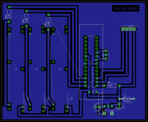
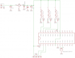
.:Controller board:.
The controller board uses 3 sliding potentiometers. The ATMEGA328p (overkill, i know) is used to take in the voltage that is divided from the pot. The data is then transmitted via the Xbee transceiver to the chandelier. **Note: There is an error in the sensitivity of the slider pot. It is either a voltage division issue or just the sensitivity of the elements sweep. I will update when i change it, or comment if you change it.
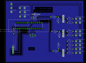
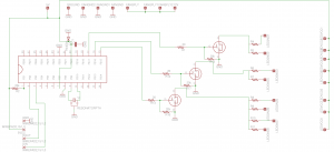
.:Chandelier Main Board:.
The chandelier has 9 LED’s 3 of each color. The LED’s are driven by a set of 3 mosfets which are connected to another ATMEGA328 (overkill again). The mosfets are connected to pwm pins on the atmega. When a valid data packet is received from the control board or computer the chandelier will respond by varying the pulse width to each channel (RGB).


Fiber Optic Chandelier Prototype by Bill Heaster is licensed under a Creative Commons Attribution-NonCommercial-ShareAlike 3.0 Unported License.


