Fiber Optic Chandelier V2
.:Intro:.
This is the write up for version 2 of the fiber optic chandelier. Some things
that won’t be discussed are the electronics, and main lighting assembly.
Fortunately this information can be found here.
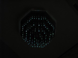
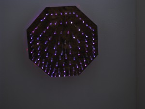
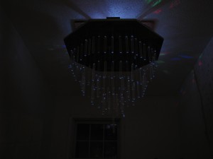
Diffusers
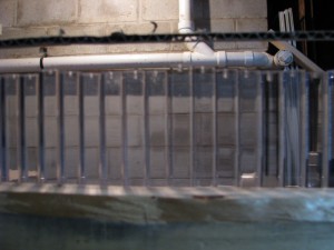
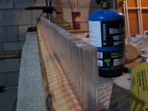
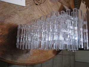
The original diffusers were very fragile and prone to breakage. They were also more labor intensive than the following procedure. The diffuser is what gives the chandelier it’s shape and overall look. To balance cost, prep time, and cosmetic appeal, clear acrylic dowel was used for this purpose. The dowel is cut into lengths of 6″ using a miter box and a jig. This will allow sufficient weight to keep the filaments straight while hanging. The ends of the dowel are then filed flat and re-glazed with a butane torch. Be careful not to leave the flame to close to the acrylic for to long. This will cause the end to burn and bubble.
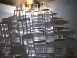
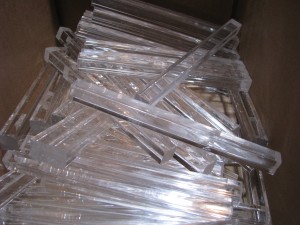
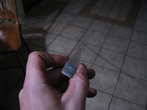
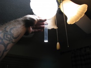
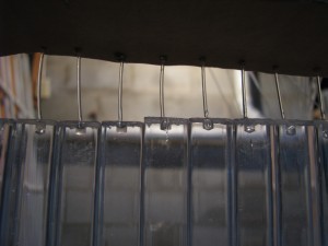
Once the dowels are cut and glazed it is time to drill a hole for the fiber optic filament to rest in. For this an 1/8″ diameter drill bit was used on a press. The bit was placed approximately 3/16″ into the end of the dowel. If desired the end that was drilled can be re-glazed to allow maximum light penetration into the diffuser. Now that the holes are drilled the dowels need to be supported so that the filaments can be placed inside the hole and allowed to rest while the epoxy used to retain them dries. To do this a 2×4 is placed on its side. The dowel are then tapped onto the board with the holes facing upward. Once secure a piece of cardboard with holes poked in it can be used to properly place the filament into it’s respective diffuser. When all filaments are in place a tube of “5 minute epoxy” can be used with an applicator tip to distribute epoxy, locking the filament in place. Allow the epoxy to cure for about 24 hours then remove the diffusers from the 2×4 support.
Frustum
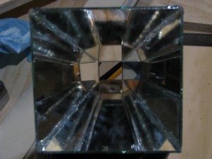
The frustum consists of mirrors used to diffuse the light before entering the filaments. The previous prototype had an issue, particularly while producing the color white, due to the spacing between the filaments and the light source. This could have been solved by using RGB LED’s versus an array of single colored LED’s. Yet there were none cheaply available that fell within the required wattage ratings. Instead the original lighting rig that was created for the version 1 prototype was modified to serve this diffusion purpose.

A thin “wall tile type” mirror was used. This is cheap and you have to buy a pack of 10 so you can screw up a few times. Lay out the pieces for your desired dimensions and cut on the glass side(not the mirror side) with a rolling type glass cutter. Note that it is best to only make one score on the glass, place it on the edge of a table so that the score line and the edge of the table are aligned. Then press downward on the piece until it snaps. It is not tempered….Wear gloves.

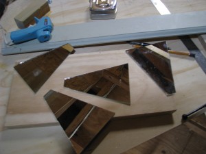
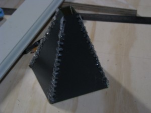
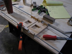
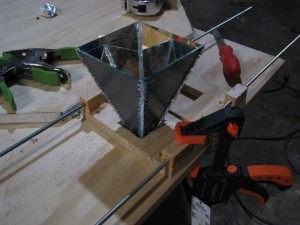
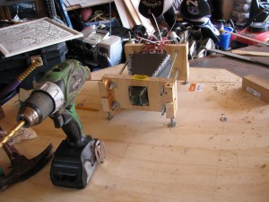
To assemble the frustum place the larger ends of the cut mirror pieces together in a square and lean them in on each other until all the seams align just right. I used a pretty ghetto procedure of hot glue stitching to keep the pieces together. Duct tape may have been a good solution as well. To support the added weight of the frustum bracing was added in the form of wood and threaded rod to keep the enclosure in one piece.
Enclosure
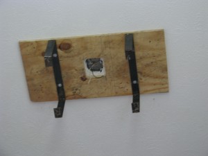
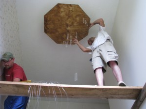
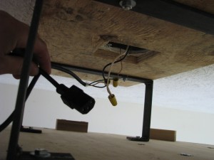
Probably the most dramatic change from the original prototype was the enclosure design and construction. Those who said to design from the ground up has never designed something that hangs from the ceiling. After getting past the learning curve a structure was created that is severely over engineered. Using a piece of plywood to span two ceiling joists. The 3/8″ steel brackets are through bolted with washers into the plywood. The base of the unit is used in placement of the filaments as well as a platform to stage the electronics and lighting rig. Furniture anchors were epoxied into the plywood, the steel bolts into these, secured with locktite, then a 1/4″ screw is placed into a separate hole directly into the backside of the plywood.
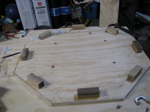
The plywood is a pine veneer, sanded. For this particular project it was cut into an octagonal shape. To make things easier on you, every corner should be at 22.5 degrees and of equal distance. 1/8″ holes were drilled in a pattern on the plywood face. This will be where you place your filaments. You can choose any layout you like. Once the base is hung the process of setting the filaments begins. Several hours of frustration later you will realize that you should have fed the filaments into the conduit compression connector as you fed them through. Several more hours of finding missing filaments done by shining a flashlight into the bottom of the diffuser and looking up top to see the glowing end. Once you get close to the desired height of your diffusers you can retain its position using a cheap close pin. If you can find small ones it would make your life way easier. Also when initially setting the position of the filaments, set them higher than you think you need to. It is much easier to pull them down then to have to raise them up and re clip the close pin with 100 filaments moving all around.
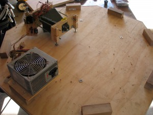
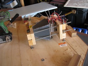
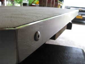
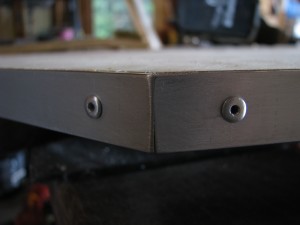
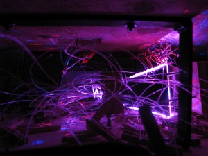
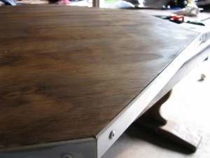
Side panels were created using clean pine, sanded and stained. Balsa wood was used to provide a backing for the side panels. The panels have a countersunk hole with wood hole plugs to cover the screw holes. The two types of pine add a nice contrast, combined with the polished aluminum edge makes it look pretty slick. Since the structural plywood layer was an after thought the side panels are 3/4″ lower than the ceiling. This actually worked out quite well. Plastic window screen material was used at the top of the panels and any light that was caught inside of the unit was dispersed across the ceiling. Adding a nice ambient effect.

2 comments
Leave a Reply
You must be logged in to post a comment.
awesome job
Why thank you GHHT!