Adding ambient lighting effects to an old oversized clock
This old Coca-Cola clock was going to be trashed so my room mate brought it back to the house. The face of the clock is covered with a clear acrylic dome. The backing of the clock is a white translucent piece of acrylic, This would make a perfect source for diffusing some RGB LED’s. The clock was torn apart, the back of the clock projects outward and offers a lot of room to add some good stuff. Since this project was started at 8:00pm we ended up using parts that I already had on hand. Below is a list of materials I used. Note, I didn’t have a wall-wart powersupply so I whipped up my own.
- perf boards
- 16mhz crystal
- 5v regulator
- 12v regulator
- 12v AC-AC transformer
- Full wave Rectifier
- Decent sized polarized capacitor
- ATMEGA328-PU
- 6 x RGB LEDS (common cathode)
- 12 x 100 Ohm resistor
- 6 x 150 Ohm resistor
- 2 x .33uf ceramic cap
- 3 x .1uf ceramic cap
- lots of wire
- 3 x PNP transitors
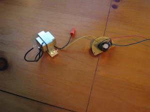
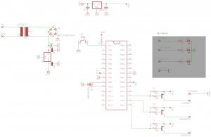
Pretty simple stuff here. The 2 legs of the transformer are tied in parrell with the 120AC that is going to the clock mech. The transformer board brings the voltage down to 12v AC. From there it gets rectified and smoothed by the capactor to produce a nice even 12VDC output. This output goes into the logic board.
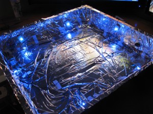
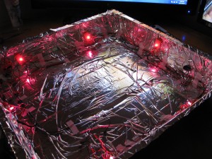
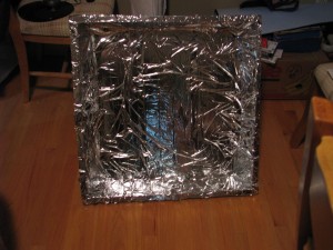
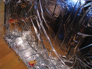
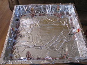
Before anything was built or installed we took some spray adhesive and stuck a fireblanket that was found in a cheap firstaid kit to the back to create a reflective surface. The LED boards contain 1 rgb led, 3 resistors, and 4 wires for each lead. The boards are attached via tape and 4 wires are ran around the inside peremiter of the clock enclosure to connect them together.
The regulated 12V coming from the power supply is controled with a switch on the outside of the enclosure. It feeds the logic board which is powered by an AVR ATMega328. Yes it is overkill, but I had one and used it. The logic board regulates the volatage down to 5v. It uses 3 PWM digital Outputs to control transistors which will adjust the brightness of each color channel.
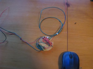
it’s a hack but this is the logic board without the ATmega chip installed.
The first lighting test worked flawlessly the first time. The reflective backing also worked better than expected. The lighting was a little to concentrated on the face of the clock so for the final pictures we angled them toward the reflective backing to distribute the light more evenly.
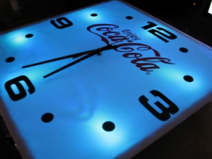
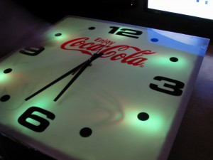
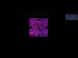
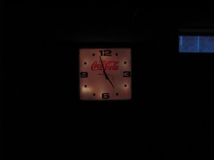
Here are some pictures of the finished product. The light is evenly distributed and the transition of the animations are fairly smooth. I would say a good hack for 8 hours worth of work. You can find the simple code i used in the CodeBank.
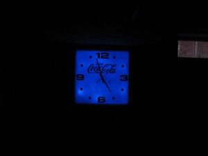
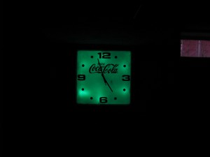
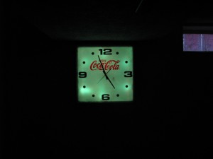
The lighting transitions of the clock from Apex Logic on Vimeo.
